What Level Sensor Should a Fertigation Stock Tank Use
A practical guide to low level shutoff continuous monitoring and refill alarms
 Lena Schmidt
Disclosure: We may earn a commission if you purchase through links on this page, at no additional cost to you.
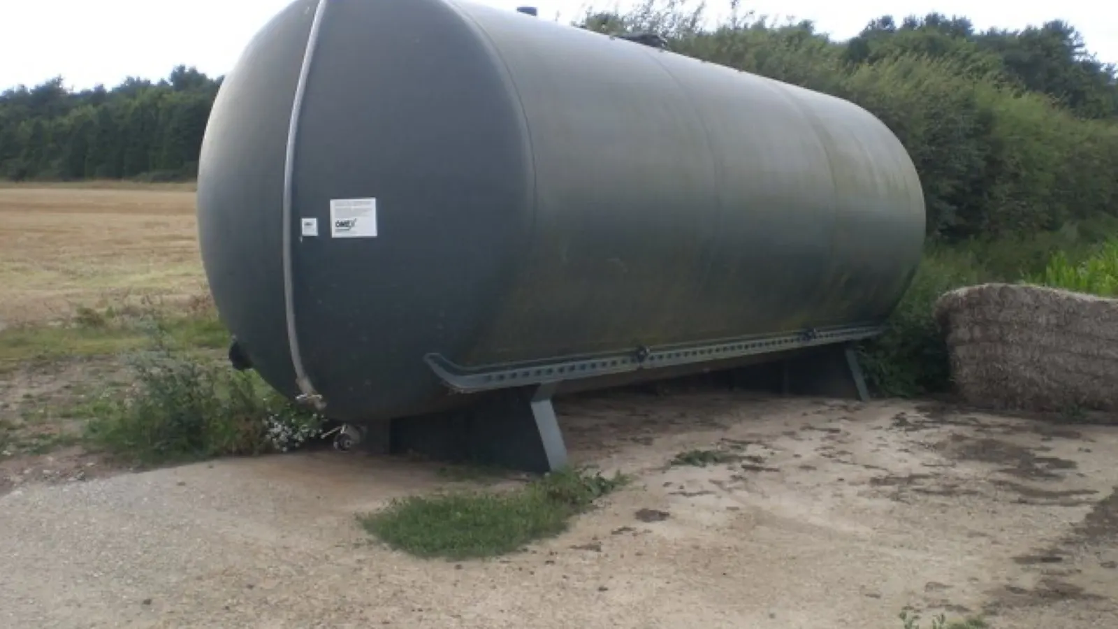
The right level device depends on what the tank must do when the reading changes. If the only critical action is to stop an injector before the suction line draws air, a two-stage float or level switch is usually the most direct starting point. If the operator also needs remaining volume, refill planning or remote trend data, a continuous ultrasonic transmitter can add useful information. It should not automatically replace an independent low-low shutdown.
This guide is for greenhouse, nursery and field fertigation stock tanks. It owns the level-measurement and interlock decision. Nominal-versus-working tank capacity, A/B channel architecture and mixing-method selection are separate decisions and are outside the scope of this guide. The question is not which sensor has the most impressive range; it is which signal remains trustworthy in the actual fertilizer, tank geometry and control loop.
Start with the failure you are trying to prevent
| Control job | Useful signal | Typical action |
|---|---|---|
| Warn that the operator must prepare or refill stock | High/low threshold or continuous level | Alarm, message or batch-planning record |
| Prevent the injector or transfer pump from running dry | Low-low switch located above the pickup limit | Stop the metering pump or close the chemical valve |
| Estimate remaining stock and consumption | Continuous level with a documented tank geometry | Display volume or trend only after calibration |
| Stop an overfill during automatic refill | Independent high-level switch or overflow protection | Close the fill valve or stop the refill pump |
| Verify that the tank is actually feeding | Level trend plus injector/flow feedback | Raise a fault when level does not change as expected |
A single sensor can report a plausible number while the safety action fails. ProMinent’s dosing-pump guidance separates a warning stage from a later pump shutdown, and specifies a low-level switch with two normally closed contacts for that purpose. The architecture matters more than the label “level sensor.” [E01]
Float switch, continuous transmitter or both
| Option | Where it fits | What the buyer must verify |
|---|---|---|
| Two-stage float or level switch | Small or medium tank; direct low-level alarm and pump permission | Wetted material, switching logic, deadband, mounting height and relay/interface |
| Ultrasonic 4–20 mA or RS485 transmitter | Inventory monitoring, refill planning and PLC or remote dashboard | Blind zone, foam, condensation, tank geometry, output scaling and chemical-vapour tolerance |
| Hydrostatic or submersible transmitter | Closed or deep tanks where top access is difficult | Specific gravity, probe material, cable sealing, sediment and zero drift |
| Independent high and low switches | Automatic refill or safety-critical systems | Fail-safe contact state, separate power path and proof that one failed sensor cannot defeat both limits |
Float switches are discrete devices. They tell a controller that a level has crossed a point; they do not measure the full tank volume. A continuous transmitter is useful for monitoring, but its displayed percentage is only meaningful after the tank shape, sensor reference, blind zone and working-volume marks have been mapped. Do not turn a catalogue range into a usable stock-volume claim.
Set the levels from the pickup point, not the tank label
The low-low level should be defined from the actual suction assembly. Mark the height at which the pickup, foot valve or pump intake can begin to draw air or a concentrated heel. Place the shutdown threshold above that point, with enough deadband to prevent a small surface wave or mixer movement from cycling the relay. A separate warning level should leave time to prepare stock or switch to a safe batch.
For a refill system, add a high-level stop or overflow path. The high limit must be independent of the low-level logic; otherwise one stuck float can permit both dry running and overfill. Source and backflow protection are separate questions, but the stock-tank level interlock still needs its own test record.
The physical location matters. A float mounted beside an agitator shaft can chatter. A sensor under a return jet can see turbulence rather than tank level. A transmitter with a large blind zone may be unusable in a short tank even though its headline range is several metres.
When an ultrasonic reading is useful and when it is not
Non-contact ultrasonic measurement avoids placing electronics or a probe in the fertilizer. It is attractive for a large covered tank, a remote dashboard or a process that needs a consumption trend. The trade-off is an acoustic measurement path: foam, condensation, splashing, a tilted surface, a narrow lid opening and a dead zone near the transducer can all change the return signal.
If the tank is actively aerated or the surface is heavily disturbed during mixing, capture a stable reading after the defined settling interval or use a separate discrete shutdown switch. A stable display during a calm water test is not proof that the same transmitter will behave in a concentrated, foaming fertilizer solution.
Chemical compatibility is a control requirement
The sensor body is part of the wetted system. Record the fertilizer formulation, concentration, pH, temperature, cleaning chemical and expected hold time before choosing PVC, PP, PVDF, stainless steel, a cable jacket or a seal. “Chemical compatible” without a named medium, concentration and temperature is not a usable acceptance statement.
A float that works in clean water can swell, stick or lose buoyancy in a concentrated stock. A metal probe can corrode or change the solution boundary. A hydrostatic sensor can be affected by density changes. The supplier should identify the exact wetted materials and provide a compatibility basis for the buyer’s formulation; do not transfer a material claim from another product family.
Failure symptoms and the first check
| Observed symptom | Likely measurement problem | First check |
|---|---|---|
| Pump stops even though the tank appears half full | Float stuck, cable logic inverted or sensor mounted in a low pocket | Test the contact state by lifting the float and compare it with the PLC input |
| Ultrasonic level jumps during mixing | Foam, splash or an unstable surface return | Record the reading with mixer off and on; check the specified blind zone |
| Displayed percentage is wrong but the switch works | Tank geometry or zero/span mapping is wrong | Measure five known levels and rebuild the level-to-volume table |
| Low alarm arrives after the pump has already lost prime | Shutdown point is below the real pickup limit | Measure the intake, heel and residual volume on the installed assembly |
| Refill cycles repeatedly near the same mark | Insufficient deadband or turbulence at the float | Move the sensor away from the return jet and log the on/off levels |
| Sensor fails after a formulation change | Wetted material or seal is unsuitable | Compare the new formulation and cleaning chemical with the supplier’s compatibility statement |
A commissioning test that earns the reading
-
Fill the tank with water and mark the true reference, warning, low-low and high levels. Record the nominal tank volume, usable working volume, pickup elevation and residual heel.
-
Test every switch or output with the controller disconnected from the pump. Confirm the intended normally open or normally closed state, the alarm text and the reset/deadband behaviour.
-
Connect the interlock through the intended relay or PLC input. Prove that low-low stops the injector, that a high-level fault stops the refill path and that a power interruption leaves the system in the intended safe state.
-
Repeat the test with the actual stock solution at the normal concentration and temperature. Observe float movement, transmitter stability, cable entry, bubbles, foam and any buildup on the sensing surface.
-
For continuous measurement, compare the output with at least five manually measured levels. Use the actual tank geometry rather than assuming a linear volume relationship. Keep a separate record for a conical bottom or a tank with a low-level heel.
-
Run the agitator or recirculation system if the installation uses one. Confirm that the return stream does not move the float, blind the ultrasonic signal or create a false low reading.
-
Simulate an empty-tank event. Verify the injector stops before air enters the suction line, the alarm is visible to the operator and the system cannot restart automatically until the reset condition is deliberate.
Chemigation guidance treats interlocks as part of the injection system, not an optional accessory. UC ANR describes electronic interlocks that prevent injector operation without water flow and recommends safeguards against chemical movement and overflow. [E02]
Choose the sensor architecture by duty
| Buyer situation | Starting architecture | Do not accept without |
|---|---|---|
| One stock tank, manual refill, direct pump protection | Two-stage low-level switch on the suction assembly | Exact contact logic, mounting drawing and low-low test |
| Large opaque tank with inventory reporting | Ultrasonic transmitter plus independent low-low switch | Blind-zone data, output map, five-point calibration and foam test |
| Automatic refill from a second tank | High stop, low start and independent low-low shutdown | Deadband, overflow route, fail-safe relay and power-loss test |
| A/B stock tanks with separate injectors | One independently tested level chain per tank | No cross-wiring, channel-specific alarm text and separate reset |
| Tank has strong aeration or surface turbulence | Discrete switches or a transmitter proven under the mixing condition | Supplier test using the actual surface condition and formulation |
The safest practical design is often layered: a simple low-low switch for pump permission, a separate warning or high-level switch for operations, and a continuous transmitter for visibility. The layers have different jobs, so they should not all depend on one untested sensor.
RFQ questions for a level-sensor quote
Ask the supplier to identify the exact sensor model, wetted materials, seals, cable jacket, switching mode, output type, supply voltage, current or relay rating, temperature range, pressure rating and ingress protection. Request the mounting drawing with the tank reference, pickup height, warning height, low-low height, high limit and service access.
For a float or discrete switch, ask for the on and off elevations, repeatability, deadband, maximum switching load and whether a relay or PLC input is required. For an ultrasonic device, ask for the blind zone, beam angle, minimum tank diameter, foam or condensation limits, analogue scaling, Modbus register map and a calibration procedure. For all types, request a formulation-specific compatibility statement and a sample-test option.
Do not accept “IP68” or “4–20 mA” as a complete selection. IP rating describes an enclosure test, while the fertilizer, temperature, mounting and control logic determine whether the installed measurement is safe and useful.
Sourcing candidates for technical follow up
The following Alibaba listings are inquiry routes rather than independent approvals. Each listing link was checked to confirm it reaches the matching Alibaba product page. That confirms destination identity only; seller authorization, exact delivered variant, stock, shipping and field performance remain separate checks.
Sourcing Candidate A — IP68 float switch for discrete level control
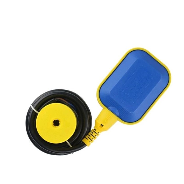
IP68 float switch for discrete level control
A discrete low-level shutdown device. The listing is positioned around water and wastewater control, so ask for the exact float material, chemical compatibility with your stock solution, switching elevations, contact logic and cable length before approving it as a low-low interlock.
- Role: Alibaba sourcing candidate
- Discrete low-level contact, not continuous measurement
- Confirm float material and contact logic
- Test the low-low shutdown in your stock solution
- MOQ: Check current listing
Marketplace observations: the listing shows an IP68 waterproof float switch for automatic liquid-level control, a 4.8 store rating with 250 reviews, a 0–70 °C field, ABS material, one-year warranty, AC 230/380 V and 15 A/8 A electrical fields. The page positions it around water or wastewater control rather than a named fertigation formulation. Treat these as platform or supplier statements. Ask for the exact float material, chemical compatibility, switching elevations, contact logic, cable length and a low-low shutdown test in the buyer’s stock solution.
Sourcing Candidate B — 0–20 m ultrasonic 4–20 mA transmitter
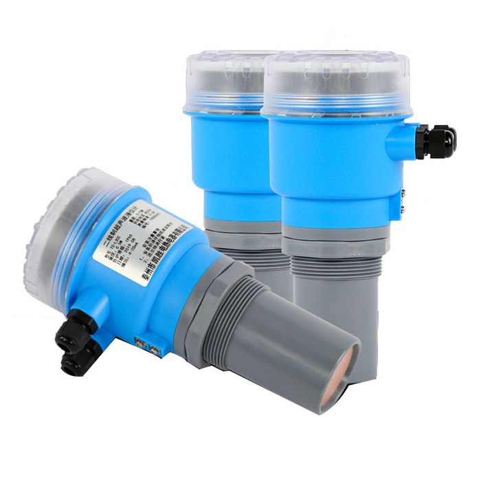
0–20 m ultrasonic 4–20 mA level transmitter
A non-contact continuous level route for inventory and refill planning. The reviewed listing shows a 0–20 m range, 4–20 mA output and a 0.2–0.5 m blind-area field; ask for the beam angle, output scaling, minimum tank diameter and a wet test under your real mixing and foam conditions.
- Role: Alibaba sourcing candidate
- Continuous 4–20 mA level signal
- Confirm blind zone and beam angle
- Keep a discrete low-low switch as backup
- MOQ: Check current listing
Marketplace observations: the listing shows a 0–20 m range, 4–20 mA output, 0.3% full-scale error, a 0.2–0.5 m blind-area field, IP65 or customized protection, ABS housing and a 7-year platform signal with 534 store reviews. These fields are not independent performance evidence and do not establish fertilizer-vapour, foam or formulation compatibility. Request the exact model datasheet, output scaling, beam angle, minimum tank diameter, blind-zone measurement, RS485 option if needed and a wet test with the real tank and mixing condition.
The candidates are deliberately not ranked. Candidate A is a direct shutdown device with visible marketplace review volume; Candidate B is better suited to continuous inventory data but introduces geometry and surface-condition questions. A buyer may need both roles, not a forced choice between them.
Questions buyers commonly ask
Can I use one ultrasonic sensor for both level display and dry-run protection
Only after a documented failure test proves the signal remains stable at the real low-low point and the control system fails safe when the transmitter, cable or power supply is lost. In many stock tanks, an independent discrete low-low switch is the simpler pump-permission device; the ultrasonic output can remain the monitoring signal.
Is a float switch enough for a 1000 L tank
Capacity alone does not answer the question. A float may be entirely suitable for a large tank if the buyer needs only a low-low contact and the mounting point is accessible. If the operator needs consumption trend, remote refill planning or multiple level values, add a continuous measurement layer and calibrate it against the tank geometry.
Should the sensor sit at the absolute bottom
Usually not. The shutdown level should protect the suction assembly from air and concentrated residue, which may be above the physical bottom. Leave a defined heel for sediment and cleaning, and place the sensor from the installed pickup drawing rather than from a catalogue tank mark.
Does a higher IP rating prove fertilizer compatibility
No. Ingress protection and chemical compatibility answer different questions. The supplier still needs to identify wetted materials, seals, cable jacket and the formulation and temperature used for the compatibility claim.
References
- ProMinent, “Suction Lances, Suction Assemblies and Level Switches for Low-Pressure Metering Pumps.” Source
- University of California Agriculture and Natural Resources, “Fertigation.” Source
- University of Florida IFAS, “Chemical Injection Methods for Irrigation.” Source
- University of Georgia CAES, “Fertilizer Injectors: Selection, Maintenance and Calibration,” B1237. Source
- Washington State University Extension, “Chemigation or Fertigation Injection Rate Worksheet.” Source
- Current social discussions were used only as language signals around low-level cutoffs, refill automation, sensor corrosion, pump dry-run concerns and tank depletion; they were not treated as engineering evidence.
- Alibaba marketplace fields for the listed products are supplier/platform statements and remain subject to RFQ, documentation, sample testing and delivered-variant checks.
Hook this up to your favourite commenting platform — Giscus, Disqus, or your own.
Continue reading
Why Does Fertilizer Concentration Change During Fertigation?
A stock-tank and injection guide for diagnosing dilution, settling and uneven nutrient delivery
Why Is My Drip Irrigation Pressure Regulator Not Working
A dynamic pressure troubleshooting guide for fertigation and low volume systems
Why Drip Emitters Clog After Fertilizer Injection
A troubleshooting and prevention guide for fertigation buyers